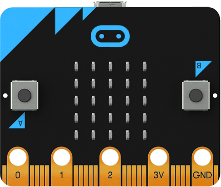
micro:bit and the Picon Zero
"A wise maker always ensures any components are serviceable before use" - Rule of Making No. 624
Now with that in mind this article would have probably been wrote earlier had it not been for a dead motor. A new one took it's place connected to a Picon Zero.
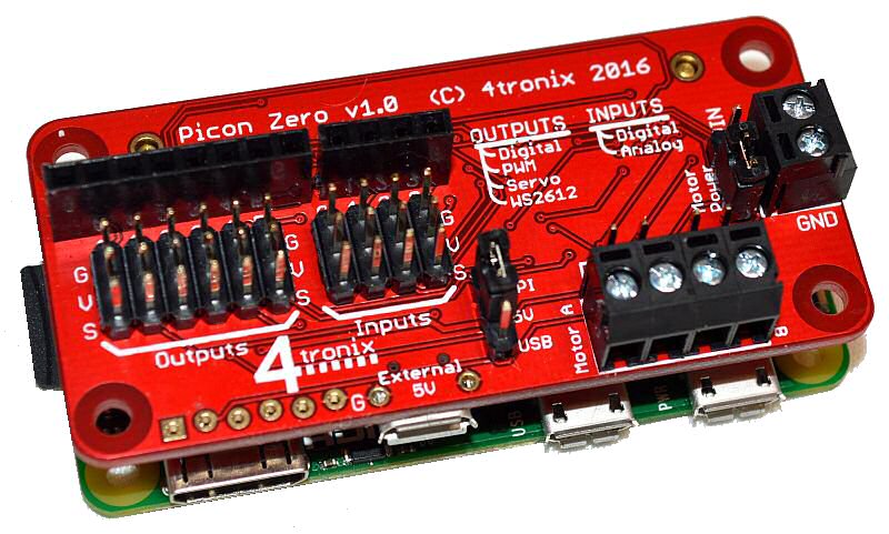
A Picon Zero is a small board designed and built by 4tronix for use with the Raspberry Pi allowing the simple control of motors as well as providing some other interesting functions. The board functions are controlled by an onboard microcontroller that communicates over the I2C bus with the host Raspberry Pi.
During a chat on twitter it was mentioned it would be amusing to see a micro:bit controlling a Picon Zero without a Raspberry Pi present.
Connecting
The obvious issue was how to connect both boards together as the micro:bit, unfortunately, lacks the 40 pin GPIO headers that are on the Raspberry Pi.
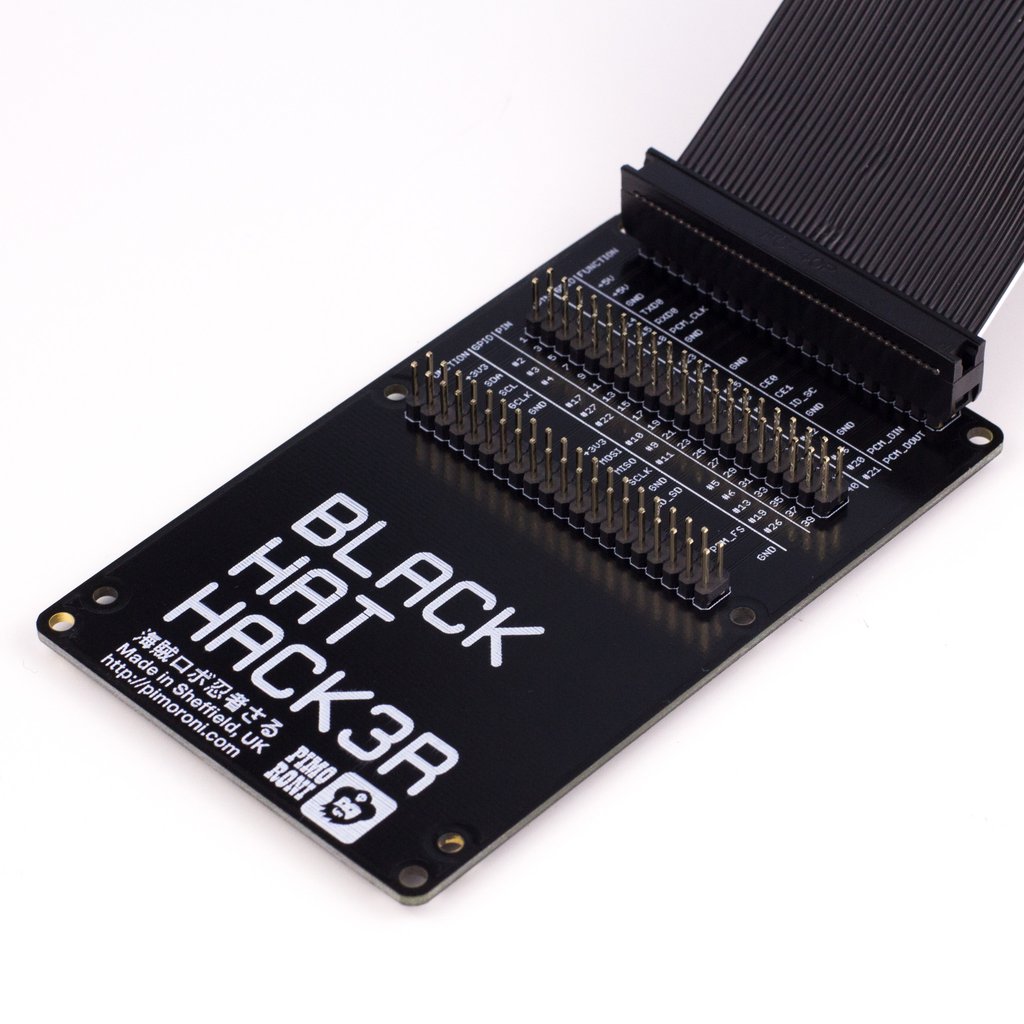
Luckily this proved not to be to much of an issue as Pimoroni has a board ideal for this, the Black Hat Hack3r board. This board provides a GPIO header for the target board and a pass-through GPIO header to connect to the Raspberry Pi. However, in between this there is another GPIO header that allows you to access the relevant pins for whatever nefarious reasons you can think of.
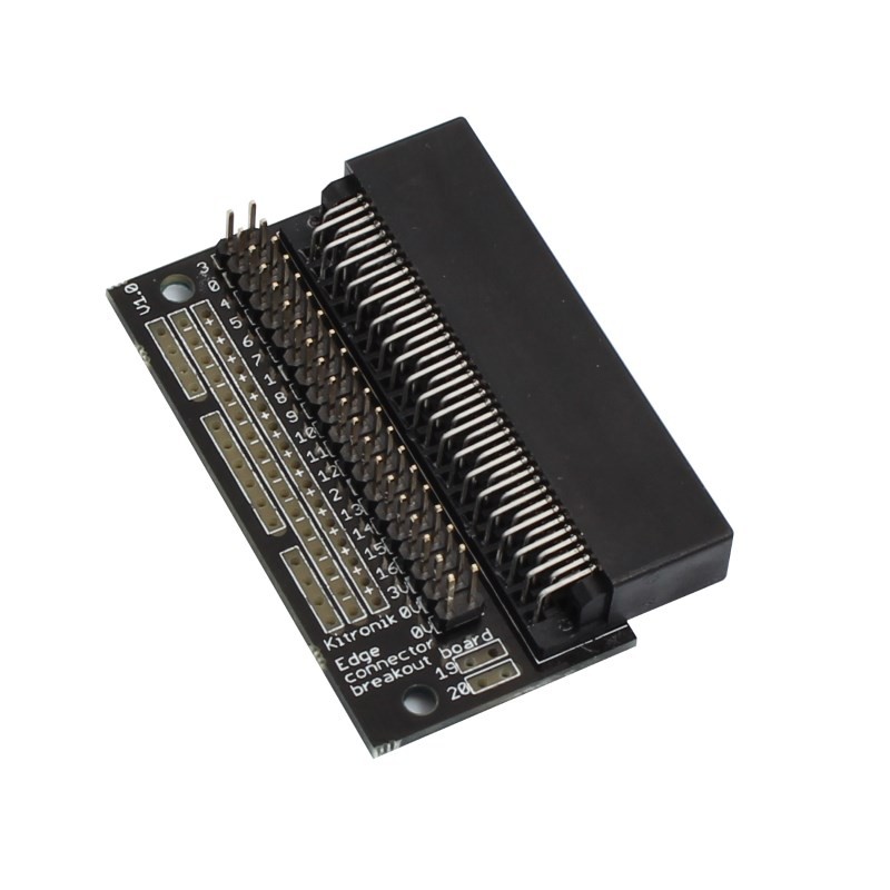
With the Picon Zero sorted it was now the turn of the micro:bit. This was an easier issue to solve as all that was required was to connect it to an edge connector breakout board. However, to allow the I2C to be used a 2 male pin header needed to be soldered onto the breakout board. Once this was done the micro:bit was ready.
Powering
Normally the Picon Zero is powered from the 5V line provided by the Raspberry Pi with an option to provide this from an external supply.
As there was no Raspberry Pi present the board was powered by the external USB connection. However it appeared that the on board microcontroller was not receiving any power. After investigating this issue was solved by providing 5V from the output pins on the Picon Zero into the 5V header. The board then started to respond.
Another option that was suggested was to power it straight from the 3.3V line on the micro:bit by connecting the 3.3V into the 5V header whilst ensuring the external 5V supply was disconnected. This also worked fine but it's probably not wise to be mixing the voltages up unless your sure what your doing.
For the motor, a normal 9V battery was connected to the terminal and the jumper set to take it's power from this source.
Talking
With both boards connected it was time to get them to talk. For this the ever trustworthy Mu was started up and a blank project flashed onto the micro:bit allowing access to the REPL interface.
The Picon Zero has a default address of 0x22 and the first thing that was done was to instruct it to provide its board and firmware revision numbers.
MicroPython v1.7-9-gbe020eb on 2016-04-18; micro:bit with nRF51822
Type "help()" for more information.
>>> from microbit import *
>>> i2c.write(0x22,bytearray([0x00]))
>>> output=i2c.read(0x22,2)
>>> print(output)
b'\x02\x08'
This showed that the Picon Zero was responding to the requests from the micro:bit.
Now it was time to see if the a motor could be turned of and on. For this to happen the Raspberry Pi Picon Zero library listed the commands as:
bus.write_byte_data (pzaddr, motor, value)
pzaddr is the I2C address of the Picon Zero, motor will either be 1 or 0 dependent on which motor you want to move and value is the speed/direction required.This should be set between -128 and +127.
Converting this to a micropython format, this became:
Turn motor on: i2c.write(0x22,bytearray([0x00,80])
Turn motor off: i2c.write(0x22,bytearray([0x00,0])
The following was passed to the micro:bit and the motor functioned normally:
MicroPython v1.7-9-gbe020eb on 2016-04-18; micro:bit with nRF51822
Type "help()" for more information.
>>> from microbit import *
>>> motorOn = bytearray([0x00,80])
>>> motorOff = bytearray([0x00,80])
>>> i2c.write(0x22,motorOn)
<slight pause to be impressed by spinning motor>
>>> i2c.write(0x22,motorOff)
Next step is to create a library to use the Picon Zero with the micro:bit.
Further info
Picon Zero:
http://4tronix.co.uk/piconzero/
https://github.com/4tronix/PiconZero
Black Hat Hack3r:
https://shop.pimoroni.com/products/black-hat-hacker
Edge connector break out:
https://www.kitronik.co.uk/5601b-edge-connector-breakout-board-for-bbc-microbit-pre-built.html
Stop Press
The bit:2:pi, which conveniently combines all the micro:bit edge connector break out with connections for a hat is now available here. A general introduction may be found in this post