A few notes on I2C and the Picon Zero....
Picon Zero is an Intelligent robotics controller for the Raspberry Pi. A built-in processor handles all the direct communication between the parent controller and any attached devices and motors.
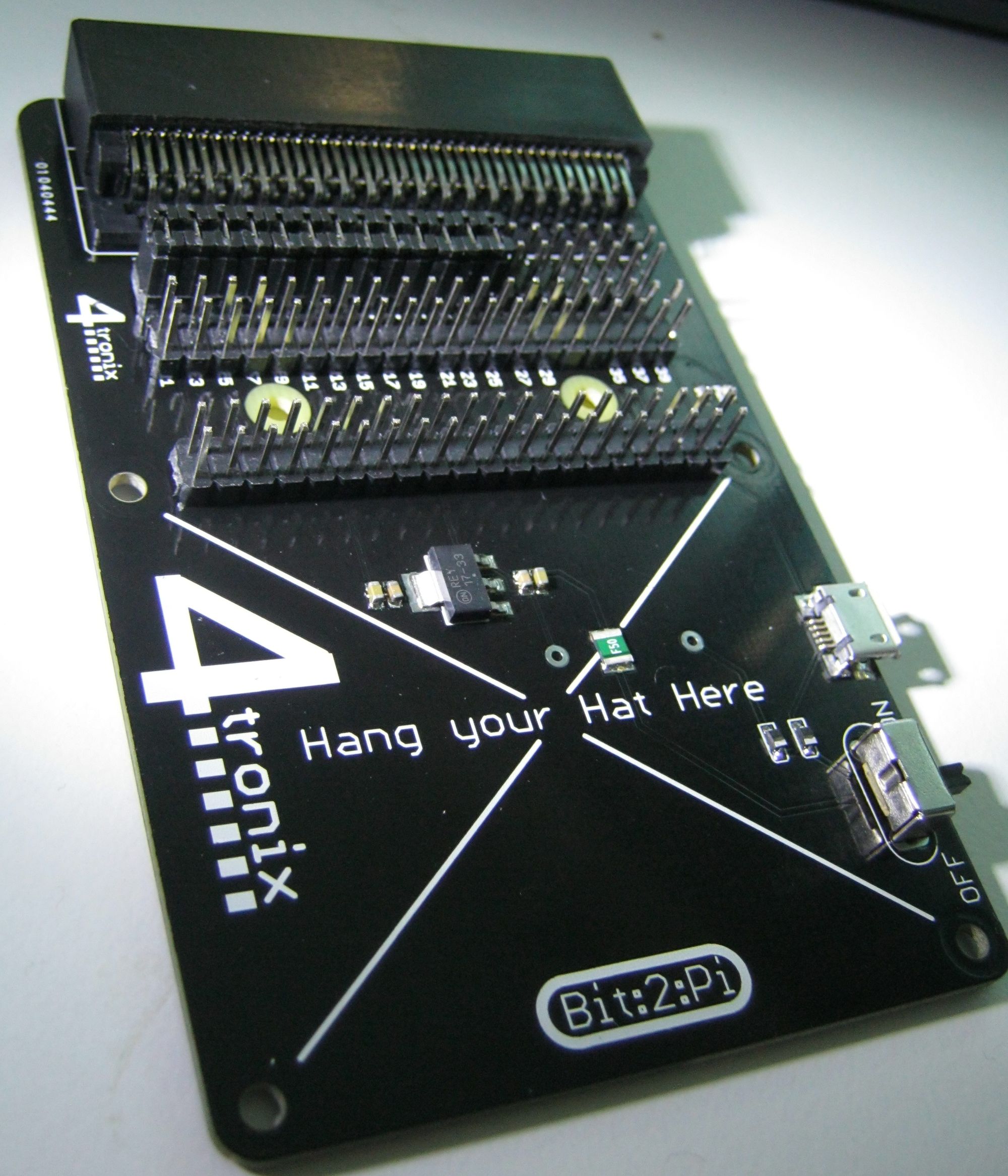
Whilst primarily an add on for the Raspberry Pi, due to it using I2C for communications, it is possible to use it with other small board controllers such as the micro:bit.
This guide will show you the basics and give you a foundation from which to develop further skills.
Also, whilst primarily aimed at use with the PiCon Zero, the techniques can also be used with other HATs or devices that are controlled via i2c.
Whats i2c?
I2C is a communication protocol that was created in the eighties by Phillips Semiconductors. It's normally used for short distance communication between peripheral devices and processors.
At a basic level devices communicate over a 2 wire bus. On each bus there will be a master which controls the other slave devices. Every device on the bus, apart from the master, will have a unique address. These addresses allow the master to talk to individual devices and to instruct them to carry out any functions.
A more detailed explanation can be found here: https://learn.sparkfun.com/tutorials/i2c
Connections
As the micro:bit edge connector and the HAT standard are physically incompatible, third party expansion boards are required. Examples of which are as follows:
-
Kitronix micro:bit edge breakout connecting to either a Pimoroni black hat hack3r board or via the HAT mounted on a breadboard.
Setup
Once everything is connected and the micro:bit is connected to your laptop via USB then start Mu.
As we will be using REPL, the first thing we will need to do is flash an empty project onto the micro:bit. This will set up an environment that will allow the 'real time' entry of code to the micro:bit.
First steps...
The first thing that needs to be done is to find the i2c address of the PiCon Zero. The documentation shows that this address is 0x22.
With this we can now talk to the the PiCon Zero and request it to provide its Board and Software revision numbers. This information is kept in register 0, which is a read only register.
For this value to be read we first need to write the address of the register 0, 0x00 to the Picon Zero. This will instruct the PiCon Zero to read the contents of register 0 and make them ready for reading. The next command is to read the values from the device.
This can be seen when entering the following code:
from microbit import *
i2c.write(0x22,bytearray([0x00]))
output=i2c.read(0x22,2)
print(output)
This should result in the following being displayed:
b'\x02\x08'
The display should now look similar to the following:
>>> from microbit import *
>>> i2c.write(0x22,bytearray([0x00]))
>>> output=i2c.read(0x22,2)
>>> print(output)
b'\x02\x08'
i2c.write() is the method that writes data onto the i2c bus. It takes three arguments: the address of the target device on the bus, the data that is being sent and if you want to repeat.
i2c.read(), in contrast, reads data from the target device. It also takes three arguments: the address of the target device on the bus, the amount of bytes to be read and if you want to repeat.
As can be seen using devices, on an i2c bus is a case of writing commands and, if required, data and reading the responses generated.
Exploring the registers
The Picon Zero has the following registers availiable:
| Register | Name | Type | Values |
|---|---|---|---|
| 0 | MotorA_Data | Byte | -100 (full reverse) to +100 (full forward) |
| 1 | MotorB_Data | Byte | -100 (full reverse) to +100 (full forward) |
| 2 | Output0_Config | Byte | 0: On/Off, 1: PWM, 2: Servo, (3: WS2812B) |
| 3 | Output1_Config | Byte | 0: On/Off, 1: PWM, 2: Servo, (3: WS2812B) |
| 4 | Output2_Config | Byte | 0: On/Off, 1: PWM, 2: Servo, (3: WS2812B) |
| 5 | Output3_Config | Byte | 0: On/Off, 1: PWM, 2: Servo, (3: WS2812B) |
| 6 | Output4_Config | Byte | 0: On/Off, 1: PWM, 2: Servo, (3: WS2812B) |
| 7 | Output5_Config | Byte | 0: On/Off, 1: PWM, 2: Servo, (3: WS2812B) |
| 8 | Output0_Data | Byte | Data value(s) |
| 9 | Output1_Data | Byte | Data value(s) |
| 10 | Output2_Data | Byte | Data value(s) |
| 11 | Output3_Data | Byte | Data value(s) |
| 12 | Output4_Data | Byte | Data value(s) |
| 13 | Output5_Data | Byte | Data value(s) |
| 14 | Input0_Config | Byte | 0: Digital, 1:Analog, 2:DS18B20, 3:DHT11 (NB. 0x80 is Digital input with pullup) |
| 15 | Input1_Config | Byte | 0: Digital, 1:Analog, 2:DS18B20, 3:DHT11 (NB. 0x80 is Digital input with pullup) |
| 16 | Input2_Config | Byte | 0: Digital, 1:Analog, 2:DS18B20, 3:DHT11 (NB. 0x80 is Digital input with pullup) |
| 17 | Input3_Config | Byte | 0: Digital, 1:Analog, 2:DS18B20, 3:DHT11 (NB. 0x80 is Digital input with pullup) |
| 18 | Set pixel Brightness | Byte | 0 - 255. Scaled max brightness (default is 40) |
| 19 | Update Pixels | Byte | dummy value - forces updating of neopixels |
| 20 | Reset | Byte | dummy value - resets all values to initial state |
Read Only Registers
| Register | Name | Type | Values |
|---|---|---|---|
| 0 | Revision | Word | Low Byte: Firmware Build, High Byte: PCB Revision |
| 1 | Input0_Data | Word | 0 or 1 for Digital, 0..1023 for Analog |
| 2 | Input1_Data | Word | 0 or 1 for Digital, 0..1023 for Analog |
| 3 | Input2_Data | Word | 0 or 1 for Digital, 0..1023 for Analog |
| 4 | Input3_Data | Word | 0 or 1 for Digital, 0..1023 for Analog |
Values for Output Config Registers
| Mode | Name | Type | Values |
|---|---|---|---|
| 0 | On/Off | Byte | 0 is OFF, 1 is ON |
| 1 | PWM | Byte | 0 to 100 percentage of ON time |
| 2 | Servo | Byte | -100 to + 100 Position in degrees |
| 3 | WS2812B | 4 Bytes | 0:Pixel ID, 1:Red, 2:Green, 3:Blue |
Moving a Motor
As can be seen in the write only registers, motorA is controlled by register 0, address 0x00 and motorB controlled by register 1, address 0x01.
Each motor can take a value between -100, for full reverse, to +100 for full forward.
To make a motor move the required speed is wrote to the relevant register. For example the following code will make motorA move:
i2c.write(0x22,bytearray([0x00,80])
and to make it stop:
i2c.write(0x22,bytearray([0x00,0])
To make the opposite motor move substitute 0x00 for 0x01
Moving a Servo
Using a servo is slightly more involved. By default the bank of GVS pins on the board are turned off and will need to be switched to servo mode to use the servo.
Consulting the list of write registers shows that registers 2 through 7 control what mode each row of GVS pins operate under. The registers that follow, 8 through 13, accept the data that, dependent on mode chosen, is sent via the related GVS pin row. With the following example it is assumed that the servo is connected to Output0.
To start with the Output0_Config has the value 2 wrote to it:
i2c.write(0x22,bytearray([0x03,2]))
This setups Output0 as a servo control. At any point the 2 can be replaced by 0 which will turn the output off.
Once the output has been set up, the servo can have values passed to via register 8, Output0_Data, as follows:
i2c.write(0x22,bytearray([0x08,-90]) #servo fully left
i2c.write(0x22,bytearray([0x08,0])   #servo central
i2c.write(0x22,bytearray([0x08,90])  #servo fully right
Reading an input
So far only outputs have been looked at. The PiCon Zero can also be used to read values.
As seen before with using the ouput registers, we first need to configure the the relevant input. The write only registers 14 through 17 are responsible for controlling the configuration of each input.
Once configured correctly, read only registers 1 - 4 will hold the data for reading.
An example of this will be as follows:
#Set Input0_Config to Digital
i2c.write(0x22,bytearray([0x14,0]))

#Start a loop

#write the address of the register to read
i2c.write(0x22,bytearray([0x01]))

#read the selected register
i2c.read(0x22,1))

#increment loop